#TechTuesday

Everett Railroad Testing Complete

Clean-Stack.jpg

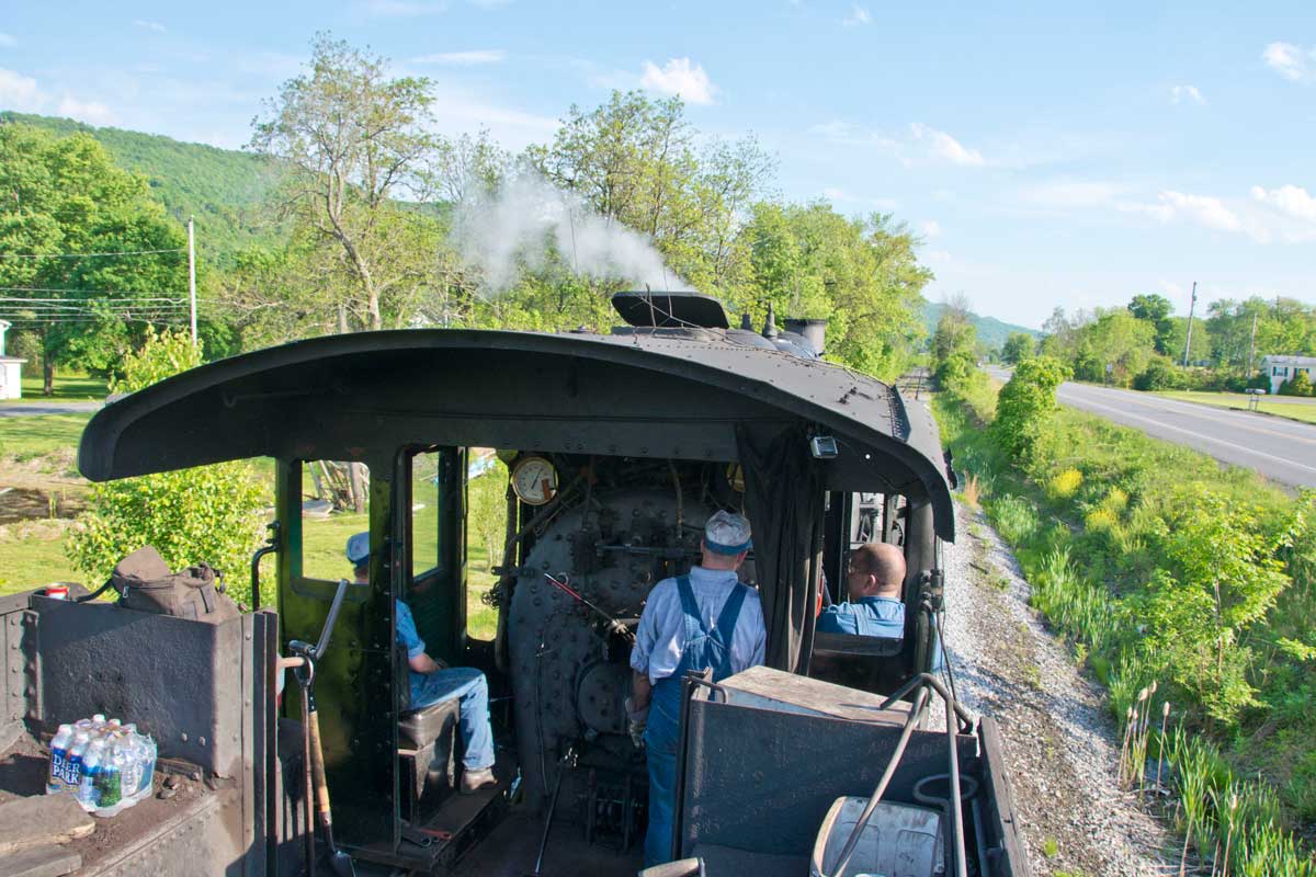
| The Coalition for Sustainable Rail (CSR), working in conjunction with the Natural Resources Research Institute of the University of Minnesota – Duluth (NRRI), have been making substantial progress in the development of sustainable solid fuels for use in boilers, including those of historic steam locomotives. The latest advancement in this multi-year project was the test of a wood-based biofuel known as “torrefied biomass” in a 1920-built steam locomotive at the Everett Railroad (EVRR) in Hollidaysburg, Penn., earlier this Summer.

Following a few months of data processing, we are pleased to announce the results of the Everett Railroad Biofuel Testing. The overall progress is positive, and we are well on the way to having a usable product.

New White Paper - Preserving Solid Fuel Firing in a Post-Coal World

This white paper addresses how economic and environmental concerns are shifting global energy markets away from coal towards natural gas and other technologies, making preservation of the skills associated with solid fuel firing increasingly difficult for heritage operators. The Coalition for Sustainable Rail (CSR), in association with the Natural Resources Research Institute at the University of Minnesota - Duluth (NRRI), is working to stay ahead of this eventuality by developing a direct coal replacement employing sustainable biomass.

Preliminary results are detailed in the paper, outlining steps being taken by CSR to perform instrumented testing and refinement of this material to-date. The project is specifically designed to reduce risk associated with development of the fuel by first conducting tests in quarter scale locomotives and then systematically moving toward larger, and larger equipment. 


UPDATE: A newer version of this paper was re-uploaded in November 2017 that includes minor corrections to the text and content. 

A Primer on the Lempor Exhaust

While we have mentioned the Lempor in some of our White Papers, and we will focus a new White Paper specifically on exhaust systems in the near future, the CSR Team thought it might be helpful to give some insights into the physics given that both Grand Canyon Railway steam locomotives No. 29 and No. 4960 are now back in service and that both have Lempor Exhausts designed by Nigel Day. 

This video, courtesy of Chris Zahrt, shows GCRy No. 29 hustling a train under stormy skies. The 1906-built 2-8-0 burns used vegetable oil and employs a Lempor Exhaust to use steam as efficiently as possible within the constraints of the historic locomotive.

Understanding drafting in steam locomotives starts in the cylinder at the point of release [C on the following diagram]. This is when the valve first opens to let exhaust steam out of the cylinder. The pressure in the cylinder at release depends largely on the cutoff selected. A long cutoff means that the cylinder has been filled with near-boiler pressure steam for the majority of the stroke, which prevents the steam from expanding much before exhaust, therefore leading to a higher pressure at release. A short cutoff allows steam to enter the cylinder for a shorter percentage of the stroke, providing a proportionately longer percentage of the stroke for the steam to expand and, thus, exhausting with a lower pressure. Regardless of the pressure at the release point, the steam pressure in the cylinder drops quickly as the steam flows out and fills the exhaust steam passages [E]. The pressure at the cylinder exit [C] will eventually stabilize to a level determined by the total cross-sectional area of the exhaust nozzle(s) and the mass flowrate of steam. This stabilized pressure is known as "back pressure."

CLICK TO ENLARGE This diagram compares a "Normal" U.S. exhaust nozzle system with the advanced "Lempor" system, as equipped on GCRy Nos. 29 and 4960. Both types share similar components of: 1) Branch Pipes [live steam]; 2) Valves [live and exhaust stem]; 3) Piston [live and exhaust steam]; and 4) Exhaust passage. Where they differ is the design of: 4A/4B) the exhaust paths; 5A/5B) the type of nozzle; 6A/6B) the design of the petticoat; and 7A/7B) the refinement in design of the stack.

Between the cylinder [3 in the diagram above] and the exhaust nozzle [5A], some of the energy left in the steam will be lost due to factors such as: passages being too small; turns being too sharp; sudden changes in passage size; passages walls being too rough; or excessive heat loss due to design / lack of insulation. In some very poorly designed locomotives, the exhaust passages can be joined in ways such that the exhaust pressure pulse from one side of the cylinder can be "seen" by the opposite cylinder which creates an artificially higher back pressure [as exhibited above near the number 4A].

Bernoulli's equation helps us understand the relationship of pressure and velocity in fluid flows. Without delving too deeply into the details, the equation tells us that a high speed flow equates to a lower pressure and a low speed flow leads to higher pressure. Taking a look at the locomotive exhaust nozzle [5A], the idea is to transfer the "pressure energy" of the steam into velocity to create a low pressure region just outside the nozzle which will suck the exhaust gasses from the firebox through the flues. For a given back pressure, a smaller nozzle opening (aka "cross-sectional area") will give a higher velocity flow and, thus, a strong draft on the fire. However, that back pressure may become high enough to start limiting the power that can be produced in the cylinders. This is exhibited in the relationship between the difference in pressure going in and going out of the cylinders. 

Normally, to get more power, one would simply increase the cross-sectional area of the nozzle opening, lowering the back pressure at the same cylinder inlet pressure and cutoff. While this may increase power, it decreases the velocity of steam exiting the nozzle and, in turn, also decreases the draft acting on the fire and drawing hot gasses through the boiler. The result would be a poorly-drafting locomotive that would have difficulty making steam to meet the improved power from the cylinders.

Whereas the above describes a traditional single nozzle exhaust, a Lempor nozzle splits the total steam flow between four separate, smaller nozzles [5B]. Assume that the total cross-sectional opening for the four Lempor nozzles is the same as a single nozzle [5A]. Under the same inlet pressure and other conditions, the local speed of the steam jet exiting the smaller openings of the four nozzles will be a fair bit higher that that of the single, larger nozzle, simply because of the relationship between opening size and velocity. This creates a stronger draft with the same back pressure. The steam locomotive designer now has more options for finding an optimal balance between cylinder power and draft.

Steam locomotive mechanical engineer L.D. Porta also introduced a converging-diverging, or DeLaval, nozzle to steam locomotive design [5B]. In all other steam locomotive exhaust nozzles that we are aware of prior to his application, the exit walls were essentially parallel to the direction of steam flow. Under subsonic conditions, the converging or narrowing section works to speed up the flow. Once the flow reaches choked conditions, basically a velocity of Mach 1, no further acceleration can be obtained and thus no more improvement in draft. The diverging, or widening, portion of the nozzle under subsonic conditions actually serves to slow down the flow and increase the pressure. However, things flip-flop once the flow goes supersonic and by allowing the nozzle to widen to the outlet, the steam jet can continue to accelerate leading to draft improvement.

The multiple nozzles also help with mixing of the steam and flue gas as they lead to more surface area of steam at high velocity in contact with the flue gas. [Note that without good mixing of the two streams, the flue gas would mostly just stay in the smokebox instead of exiting the stack and its velocity through the flues and tubes would be much lower, resulting in poor heat transfer and thus poor steaming.] While mixing takes place as soon as the steam exits the nozzle, the first section of the petticoat [6B] is specifically thought of as a mixing chamber and its proportions in concert with those of the nozzles help assure good mixing/momentum transfer from the high velocity steam to the lower velocity flue gas.

Once mixed, the steam and flue gas is in the subsonic flow region but still has a fair bit of energy left and is still flowing at a fairly high velocity. If it was just allowed to go up a straight stack to the atmosphere [7A], that energy would be lost. Therefore, the latter part of the Lempor petticoat widens out [7B], which slows the flow and increases its pressure back to that of atmospheric. This characteristic, widening stack can be seen in the diagram of No. 29 below.

As in much of fluid mechanics, it takes very careful calculation and proportioning to maximize the benefit of the system which can be significant compared to other known exhausts. Failure to do so, either through poor engineering or when physical or other constraints restrict the designer's ability to implement a properly sized system will lead to a poor performing product.


Upcoming White Paper

The CSR Team is working on a White Paper dedicated to the development of advanced steam exhaust systems, from the traditional U.S. designs through Chapelon to Giesel and Lempor. Expect more information on that in the coming month. To stay up to date on CSR, consider signing up for our email list at the bottom of this page.

Footage of First Torrefied Biomass-Run Train

This video shows the first run of the torrefied biomass test train on the Milwaukee County Zoo mainline, with footage of the train starting from the point the shop lead connects with the tracks and operating to the summit, approximately 1/2 mile. We have synced up the readings from the four thermocouples with the video footage, showing a second-by-second readout of combustion temperatures in the locomotive.

While watching the video, note that Zoo crew member, Ken Ristow, is hand shoveling loads of the small, torrefied biomass pellets into the firebox. The fuel pellets, which were graciously donated to CSR for these tests by New Biomass Energy, are much smaller than the coal typically used on a steam locomotive. We therefore modified the grates with stainless steel mesh to prevent the fuel from falling through the large pinholes. Due to the small size of the fuel, we could only build up a thin firebed (2" with biomass vs. 5" on coal), meaning there was less potential energy in the fire, resulting in the need to shovel more frequently than with coal. Likewise, NBE's pellets exhibited such good flowability, which is very important in stoker firing, that they were prone to slide off of the coal scoop.

CSR is working with research collaborator Natural Resources Research Institute and the Milwaukee County Zoo to schedule another round of testing later this year with larger, "puck" sized torrefied biomass briquettes to further verify the promising results produced from these initial tests. Likewise, we have been in discussion with standard gauge steam operators about performing full size tests in the future.

In all, the Milwaukee County Zoo tests were an extremely important scientific and risk mitigation step in this research. They allowed CSR the opportunity to collect comparative data on the combustion of coal vs. torrefied biomass (which will be made available in the coming months as part of a larger White Paper) and it proved that steam locomotives could make steam and operate safely using the alternative fuel. 

We could not have done these tests without the outstanding assistance of the Milwaukee County Zoo, the Natural Resources Research Institute, New Biomass Energy, the American Boiler Manufacturers Association, and the support of CSR's donors, including generous contributions by Bon French and Fred Gullette.


If you'd like to help make the next set of tests happen, please consider:

Diametral Speed for Pi Day

Today is "Pi Day" - the date of 3-14.16. Pi was very important to railroad engineers of yesteryear, and not just the dessert-type.

Balancing of steam locomotive driving wheels was an engineering exercise subject to much trial and error (and some success). One term often thrown around in steam locomotive technical pieces is "Diametral Speed," or the the speed when the diameter of the driving wheel (in inches) equals the speed (in mph). This “Diametral Speed” occurs at 333RPM thanks to the relationship between the circumference of the driving wheel (2πr).

Thus, when the 84” diving wheels of an ATSF 4-6-4 are rotating at 333 RPM, the locomotive is traveling at 84 mph. Likewise, when the 60” wheels of a Chinese QJ are spinning at 333 RPM, that locomotive is traveling 60 mph, and so on. Since a steam “engine,” like an automotive “engine,” is limited by maximum rotational speed (read: “redline”) at approximately 550 RPM, the larger the wheel, the higher the speed. But, since the power range of steam locomotives depend partially on the flow of steam through the pistons at certain RPMs, the smaller-wheeled locomotives develop maximum horsepower at lower speeds, which is why small driving wheels were used on freight locomotives moreso than passenger locomotives.

As to this advertisement, when cast steel wheels of Boxpok and Baldwin Disc variety came onto the scene in the late 1930’s, they allowed railroads to improve balance and reduce dynamic augment (track forces attributable to overbalance) since they were significantly lighter (and stronger!) than the traditional spoked wheel. This 1937 Baldwin ad outlines the significant improvements. More info on balancing can be found in CSR's White Papers on Steam Locomotive Balancing -www.csrail.org/whitepapers

Regardless, we hope you had a chance to eat some “pi” yesterday. Enjoy your ‪#‎techtuesday‬!

New CSR Advisor - D. Shane Meador

Shane Meador stands beside 4501 as he starts up its cross compound air pump.

Shane Meador stands beside 4501 as he starts up its cross compound air pump.

On this #techtuesday, we are pleased to announce that CSR has appointed D. Shane Meador to serve as a technical advisor of the organization. Meador is no stranger to steam, having led the rebuilding of Southern Railway steam locomotives 630 and 4501 at the Tennessee Valley Railroad Museum (TVRM). He began his railroad carrier as a summer steam locomotive fireman at the Tennessee Valley Railroad Museum in 1994 and qualified as a locomotive engineer in 1996 on steam and diesel locomotives. After being honorably discharged from the United States Navy, Meador began working for Norfolk Southern Railway as a Machinist in Chattanooga, while still continuing part time duties at TVRM coordinating the Southern 630's restoration.

Starting in 2010, Meador was offered the opportunity for a 3 year leave of absence from Norfolk Southern to manage the steam locomotive projects for use on Norfolk Southern's 21st Century Steam program at TVRM. During that time, he successfully led the extensive restorations of Southern steam locomotives 630 and 4501 back to mainline service. By creating a safe, positive, and educational atmosphere, he was able to recruit and retain volunteers throughout the project which helped to reduce labor costs significantly. Shane has operated all 4 steam locomotives currently participating in the Norfolk Southern's 21st Century Steam program on 6 Divisions traversing thousands of miles on mainline track.

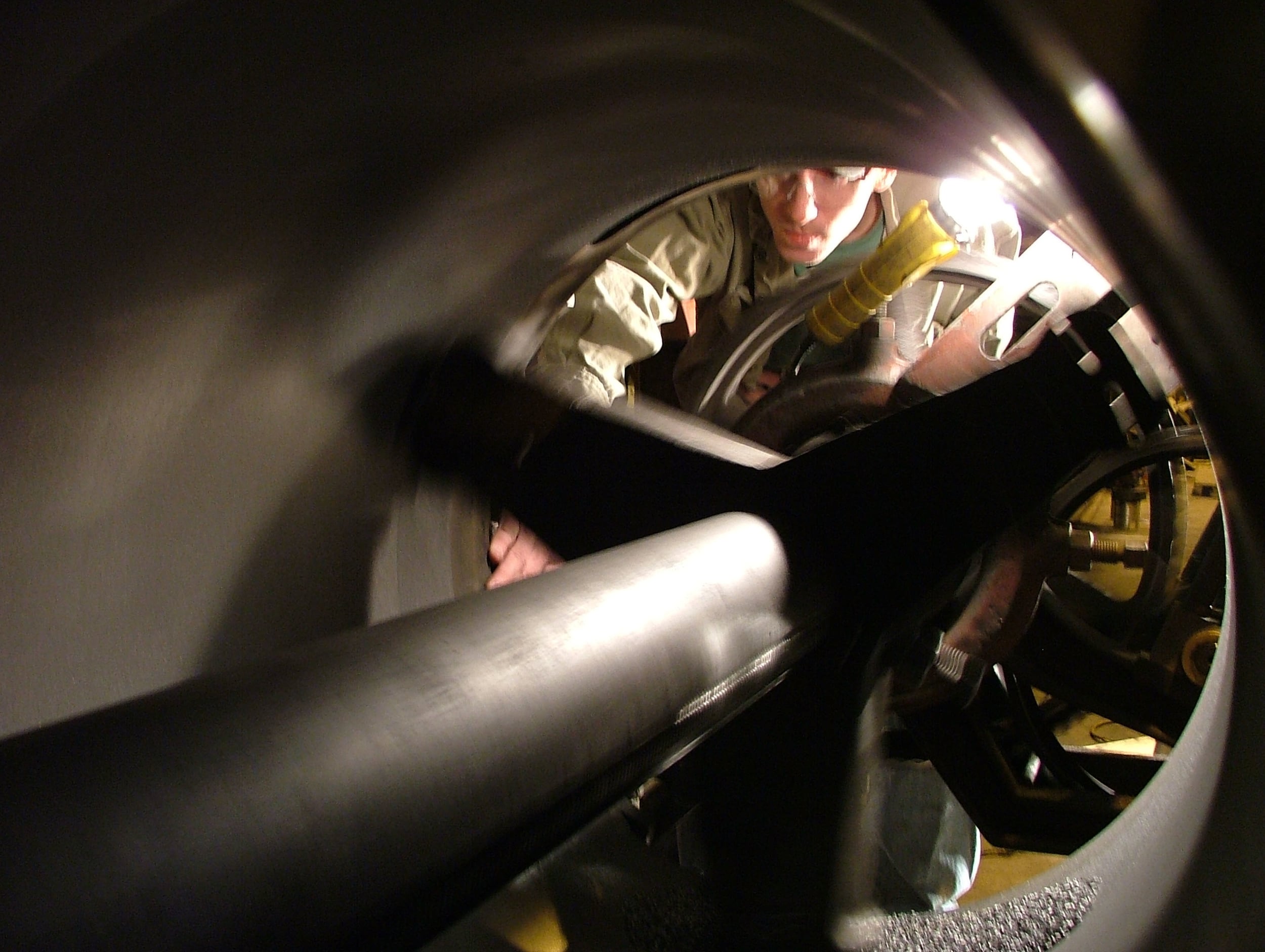
Meador keeps a close eye on cylinder boring work on Southern 630.

Meador keeps a close eye on cylinder boring work on Southern 630.

Meador's background, leadership, and experience in locomotive management, personnel management, restoration project management, maintenance, and safely operating these unique and historic machines will be of significant benefit to CSR as it continues its dedicated work to keeping historic machinery operating safely and efficiently in the 21st Century. We are excited to have his input here at CSR moving forward.