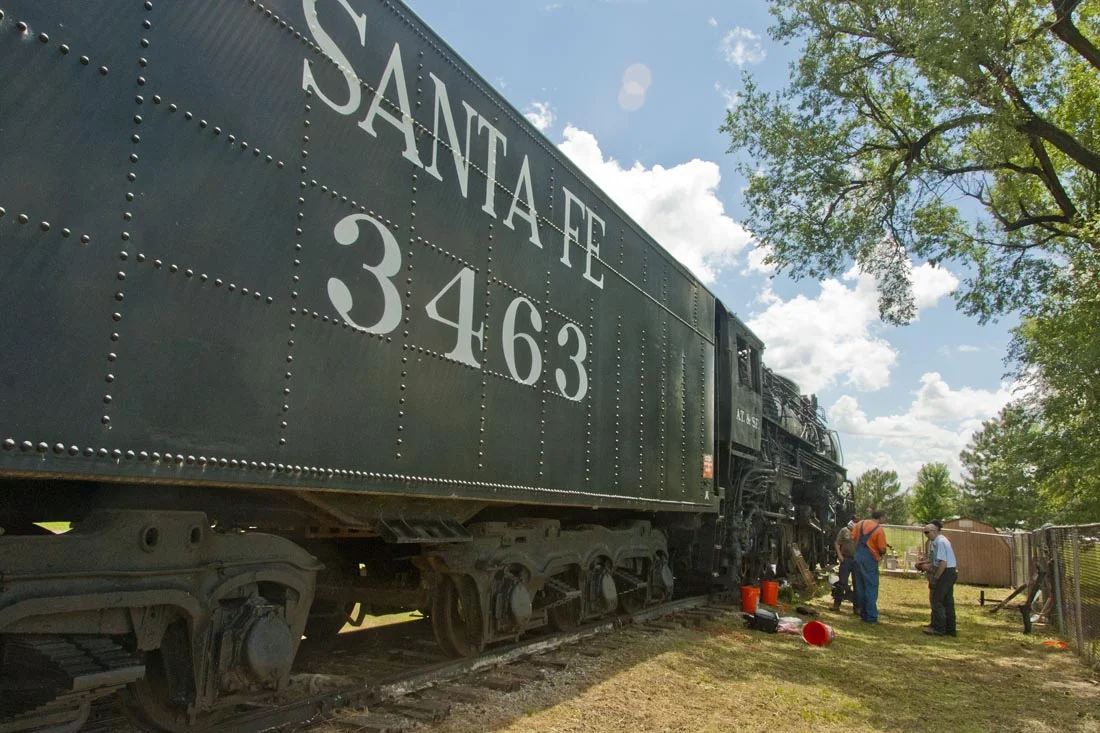
CSR sent a work crew to Topeka, Kansas, in June 2013, to prepare steam locomotive 3463 for its first substantial move in 57 years. The locomotive was placed in the park with a dedication ceremony on November 3, 1956. It sat parallel to Topeka Avenue until the mid 1980’s when, as the Kansas Expocentre was being constructed, the locomotive was moved roughly 500 feet downhill and away from the main road.
As CSR prepares to move the locomotive out of the park, it is critical to ensure that when the locomotive rolls, it does not damage itself. Because there has been little-to-no maintenance to the roller bearings since the locomotive was placed in the park, including no work to roller bearing axles and side rods, CSR needed to perform a detailed inspection and re-lubrication of those core components. To accomplish that, CSR: 1) drained, inspected and refilled all of the roller bearings on the locomotive’s axles; 2) pulled off the main rods and prepared the remaining rods to be cleaned and greased just-prior to the locomotive’s move and 3) disconnected the main rods from each crosshead, placing them on each respective running board, thereby isolating the piston from reciprocal movement during the upcoming move.
Journal BEARINGS
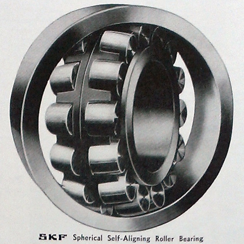
Like many mainline steam locomotives manufactured after 1930, locomotive 3463 was designed and manufactured with low-resistance roller bearings on each of its axles. Designed by ATSF and the Baldwin Locomotive Works mechanical engineering staff, the 3460-class of locomotives were some of the most powerful and modern high-speed passenger steam locomotives of their type ever designed. Unlike most other roller bearing-equipped steam locomotives of the era which featured Timken Tapered Roller Bearings, the designers decided to equip all 3460-class locomotives with SKF Spherical Roller Bearings on all lead, main, trailing and tender axles (26 bearings in total).
Invented by Swedish company SKF, the spherical roller bearing has many similar attributes to those of the tapered roller bearing, but features greater resilience in the face of misalignment and flexing of axles under stress. According to the company:
Spherical roller bearings have two rows of rollers, a common sphered outer ring raceway and two inner ring raceways inclined at an angle to the bearing axis. The bearings are self-aligning and insensitive to misalignment of the shaft relative to the housing, which can be caused, for example, by shaft deflection. Spherical roller bearings are designed to accommodate heavy radial loads, as well as heavy axial loads in both directions.
CSR contacted SKF regarding the bearings on its locomotive, including inspection protocol and lubrication standards prior to performing work on the engine. SKF indicated that the roller bearings should be drained completely, inspected visually via boroscope and refilled with appropriate, yellow-metal-safe lubricant.
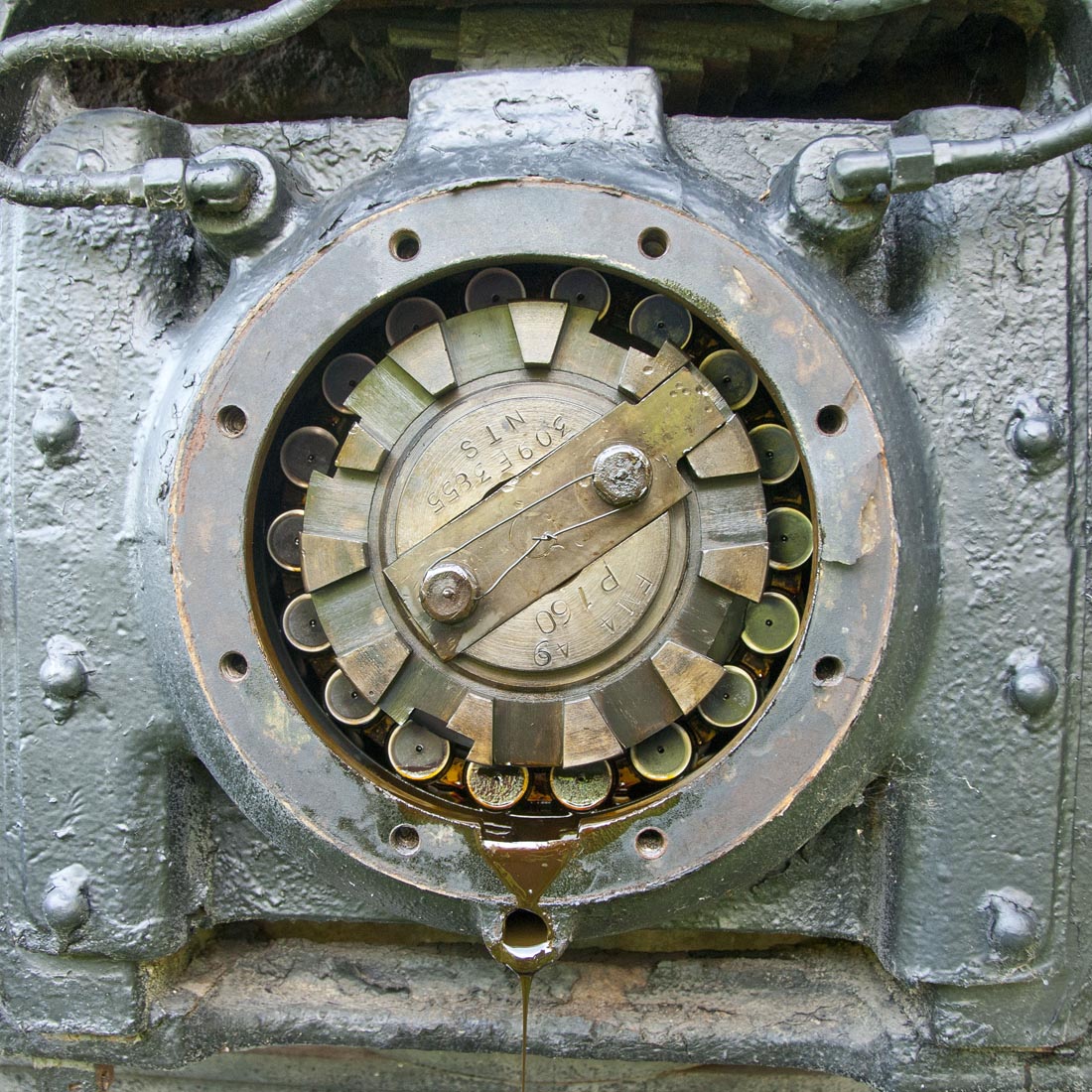
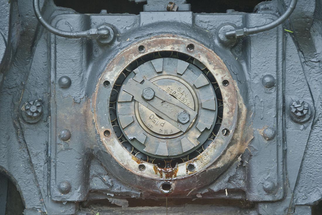
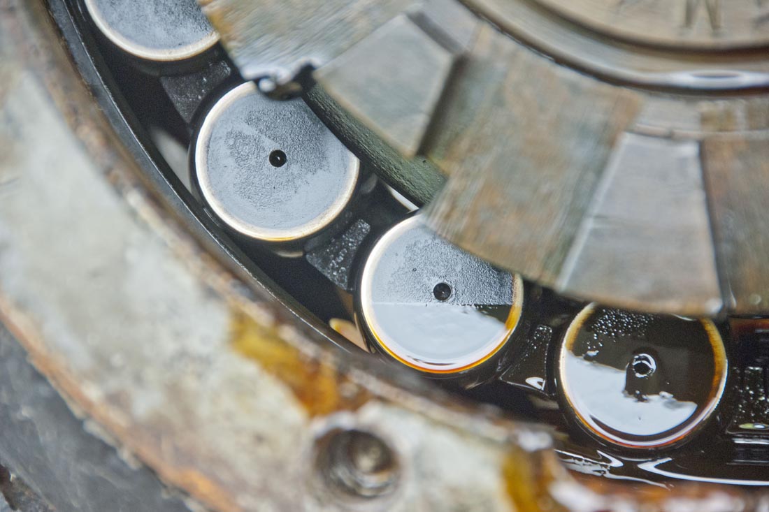
Beginning with easy-to-access trailing truck bearings, CSR began draining the half-century old bearing oil, which flowed out of the drain plug with little difficulty. Once flow waned to a trickle, the CSR crew unbolted the cast bearing covers and removed them. Unsure what to expect, CSR discovered bearings in shockingly good condition considering the total lack of maintenance. Seeing no visible pitting on any of the bearings and little contaminant in the oil, the CSR crew went about draining the remainder of the axles of their oil.
Draining lead truck and main axle bearing oil proved an acrobatic exercise. Despite having 84” driving wheels and bearing box centers half-as-high, the design of the locomotive’s brake rigging made accessing the drain plugs without an inspection pit an exercise in contortionism [see below]. Working in pairs of two, one CSR crew member would clip all safety wires on the plugs, allowing them to rotate freely, while another member would lug along a drain pan, 15” wrench, rags and mats to begin the process of draining between three and seven quarts of oil from each of the bearing boxes, dependent upon the bearing box design. Again, as draining and inspection continued, CSR was pleased at the condition of each of the bearings.
Once all bearings had been drained, CSR began the process of refilling each with fresh oil. The lead and trailing truck bearings could be easily filled with a standard funnel and pitcher, but the driving axle boxes, which had traditionally been filled via oil pump, could not be easily replenished with bucket and funnel. As an improvisation, CSR attached 10 feet of flexible tubing to the end of the funnel, snaking one end between driving wheel center openings and the frame and into the fill plug opening while pouring oil into the funnel from the outside of the locomotive.

ROD BEARINGS
The power of a steam locomotive is transmitted from pistons to a series of side rods that connect the driving wheels. In locomotive 3463’s case, each of two pistons theoretically generates up-to 130,120 lbs of force, the effective force is often much lower due to internal inefficiencies in the steam circuit common to the 3460-class, something CSR will address in its rebuild. A main rod connects the piston rod to the main driving pin, and coupling rods transmit that driving force to the remaining driving wheels. The combination of driving wheel diameter, piston stroke and diameter, boiler pressure and weight on drivers all factor into the steam locomotive’s pulling power, known as “tractive effort.”
To prevent damage to the piston and cylinder lining during its upcoming move, CSR needed to disconnect the piston rod from the main rod on each side of the locomotive, and to remove the latter prior to shipment to Minneapolis. This work entailed removing the union link, driving out the wrist pin, removing the eccentric rod and crank and positioning the crosshead in such a manner that the main rod could be removed without torsion about its brass bearing.

The first (and easiest) step was removal of the union links [1] from the wrist pins [2] [numbers correspond to diagram above]. CSR was then able to access the wrist pin [2] itself. Designed to transmit the full force of each piston, the wrist pins2 are tapered and keyed, meaning they will not rotate or loosen during high-speed operation. Using a custom-made tool to protect the threads on the pin, CSR employed a persuasive 10 lb sledge hammer to loosen the wrist pins. [2] Once the pins began to move, CSR used blocking and nylon straps to prevent the rods from binding on the wrist pins.
The crew then turned its attention to the eccentric rods3 (another easy-to-remove item) and the eccentric cranks4 (not-so-easy-to-remove). With eccentric rods [3] removed, CSR needed to remove two, 18”-long tapered pins, spread the end of the eccentric crank [4] with a wedge and carefully coerce the crank off of the end of the main axle. The eccentric crank [4] has one tapered pin that is aligned directly through the center of the main crank pin and one pin just offset, proving cinching force through the forks of the crank.
With large wrenches and persuasion of that sledge hammer, the crew had the eccentric cranks [4] removed in little time, revealing rod brasses on the locomotive that were in outstanding condition.
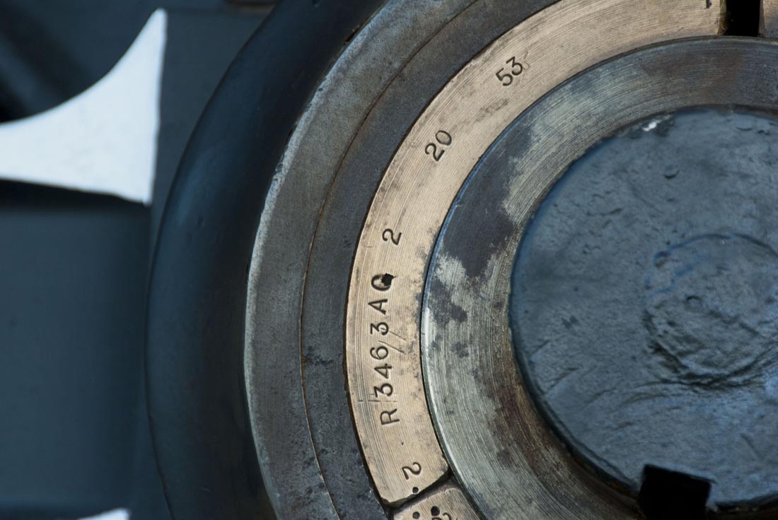
Folk lore always seems to indicate that the locomotive given to such-and-such city was rebuilt just-prior to being stuck into whatever park it currently sits. Though often apocryphal, in the case of locomotive 3463, it appears that is almost the case. The ATSF maintained inspection tags and stamped parts installed on each of its steam locomotives when work was performed to maintain a detailed record of work undertaken. The near-new rod bearings exposed when crews removed the eccentric crank read: AQ 2 20 53. This is code for work performed at the shop in Albuquerque, New Mexico, with brasses cast on February 20, 1953, meaning the bearings have very few revenue miles of operation on them.
Once both eccentric cranks [4] were removed, CSR then had to move the locomotive for the first time in 24 years to align holes in the number one driving wheel with the back side of each wrist pin [2] for removal. The length of the pin is longer than the distance between the back of the crosshead and the driving wheel, meaning an opening in the wheel center has to be lined up with the wrist pin [2] opening to allow it to be removed.
With a 20 ton jack and a bit of leverage, locomotive 3463 lurched forward with ease, rolling on newly-lubricated roller bearings. Crews moved the engine backwards and forwards, lining up the wrist pins [2] with the correct wheel opening and driving each pin the remainder of the way into the hands of waiting workers.
The main rods [5] still blocked and securely chained, the crossheads [6] needed to be pushed far enough forward to allow the rod to rotate freely and, subsequently, be removed. Using pry bars and jacks, the CSR crew moved each crosshead [6] to clearance, freeing the main rod to be removed from the mechanism. Once the steel safety straps were unbolted, CSR used a large forklift and straps to support the weight of the rod, and then removed chains and blocking, slid the rod off of each pin and hoisted them up onto the running boards.
When all brasses had been removed and stored, the revealed crank pins appeared to be in very good condition. The Alemite grease applied 57 years ago by the Santa Fe had not worn off, protecting the pins and preventing excessive corrosion.
Once the main rods were placed on the running boards, the engine and tender were separated. Of interest, the six-axle, 174,000 lb tender rolled with a simple push of two people; a tribute to the bearing construction.