White Paper Program

New White Paper - Preserving Solid Fuel Firing in a Post-Coal World

This white paper addresses how economic and environmental concerns are shifting global energy markets away from coal towards natural gas and other technologies, making preservation of the skills associated with solid fuel firing increasingly difficult for heritage operators. The Coalition for Sustainable Rail (CSR), in association with the Natural Resources Research Institute at the University of Minnesota - Duluth (NRRI), is working to stay ahead of this eventuality by developing a direct coal replacement employing sustainable biomass.

Preliminary results are detailed in the paper, outlining steps being taken by CSR to perform instrumented testing and refinement of this material to-date. The project is specifically designed to reduce risk associated with development of the fuel by first conducting tests in quarter scale locomotives and then systematically moving toward larger, and larger equipment. 


UPDATE: A newer version of this paper was re-uploaded in November 2017 that includes minor corrections to the text and content. 

Updated White Paper - Steam Locomotive Rail Wheel Dynamics 2.1

While CSR does strives to ensure that its White Papers are accurate and understandable, from time to time we receive emails from readers requesting we explain, or address, specific items from our papers. Such is the case with this re-release of an edited version of "Steam Locomotive Rail Wheel Dynamics Part 2: Mechanical Balancing of Steam Locomotives."

Two observant readers brought to our attention a handful of proposed edits to the paper, ranging from requests for clarification on certain issues to proposed modifications to aid in explaining key principles. All of the suggestions were considered by the authors and many of them were incorporated in this re-released version of the White Paper. CSR always welcomes feedback on its work, and you may always reach out to us using the CONTACT form on this website.

And, if you have yet to review our White Paper portion of the website, be sure to check out the information we have posted. We are currently working on a comprehensive White Paper on steam locomotive exhausts.

A Primer on the Lempor Exhaust

While we have mentioned the Lempor in some of our White Papers, and we will focus a new White Paper specifically on exhaust systems in the near future, the CSR Team thought it might be helpful to give some insights into the physics given that both Grand Canyon Railway steam locomotives No. 29 and No. 4960 are now back in service and that both have Lempor Exhausts designed by Nigel Day. 

This video, courtesy of Chris Zahrt, shows GCRy No. 29 hustling a train under stormy skies. The 1906-built 2-8-0 burns used vegetable oil and employs a Lempor Exhaust to use steam as efficiently as possible within the constraints of the historic locomotive.

Understanding drafting in steam locomotives starts in the cylinder at the point of release [C on the following diagram]. This is when the valve first opens to let exhaust steam out of the cylinder. The pressure in the cylinder at release depends largely on the cutoff selected. A long cutoff means that the cylinder has been filled with near-boiler pressure steam for the majority of the stroke, which prevents the steam from expanding much before exhaust, therefore leading to a higher pressure at release. A short cutoff allows steam to enter the cylinder for a shorter percentage of the stroke, providing a proportionately longer percentage of the stroke for the steam to expand and, thus, exhausting with a lower pressure. Regardless of the pressure at the release point, the steam pressure in the cylinder drops quickly as the steam flows out and fills the exhaust steam passages [E]. The pressure at the cylinder exit [C] will eventually stabilize to a level determined by the total cross-sectional area of the exhaust nozzle(s) and the mass flowrate of steam. This stabilized pressure is known as "back pressure."

CLICK TO ENLARGE This diagram compares a "Normal" U.S. exhaust nozzle system with the advanced "Lempor" system, as equipped on GCRy Nos. 29 and 4960. Both types share similar components of: 1) Branch Pipes [live steam]; 2) Valves [live and exhaust stem]; 3) Piston [live and exhaust steam]; and 4) Exhaust passage. Where they differ is the design of: 4A/4B) the exhaust paths; 5A/5B) the type of nozzle; 6A/6B) the design of the petticoat; and 7A/7B) the refinement in design of the stack.

Between the cylinder [3 in the diagram above] and the exhaust nozzle [5A], some of the energy left in the steam will be lost due to factors such as: passages being too small; turns being too sharp; sudden changes in passage size; passages walls being too rough; or excessive heat loss due to design / lack of insulation. In some very poorly designed locomotives, the exhaust passages can be joined in ways such that the exhaust pressure pulse from one side of the cylinder can be "seen" by the opposite cylinder which creates an artificially higher back pressure [as exhibited above near the number 4A].

Bernoulli's equation helps us understand the relationship of pressure and velocity in fluid flows. Without delving too deeply into the details, the equation tells us that a high speed flow equates to a lower pressure and a low speed flow leads to higher pressure. Taking a look at the locomotive exhaust nozzle [5A], the idea is to transfer the "pressure energy" of the steam into velocity to create a low pressure region just outside the nozzle which will suck the exhaust gasses from the firebox through the flues. For a given back pressure, a smaller nozzle opening (aka "cross-sectional area") will give a higher velocity flow and, thus, a strong draft on the fire. However, that back pressure may become high enough to start limiting the power that can be produced in the cylinders. This is exhibited in the relationship between the difference in pressure going in and going out of the cylinders. 

Normally, to get more power, one would simply increase the cross-sectional area of the nozzle opening, lowering the back pressure at the same cylinder inlet pressure and cutoff. While this may increase power, it decreases the velocity of steam exiting the nozzle and, in turn, also decreases the draft acting on the fire and drawing hot gasses through the boiler. The result would be a poorly-drafting locomotive that would have difficulty making steam to meet the improved power from the cylinders.

Whereas the above describes a traditional single nozzle exhaust, a Lempor nozzle splits the total steam flow between four separate, smaller nozzles [5B]. Assume that the total cross-sectional opening for the four Lempor nozzles is the same as a single nozzle [5A]. Under the same inlet pressure and other conditions, the local speed of the steam jet exiting the smaller openings of the four nozzles will be a fair bit higher that that of the single, larger nozzle, simply because of the relationship between opening size and velocity. This creates a stronger draft with the same back pressure. The steam locomotive designer now has more options for finding an optimal balance between cylinder power and draft.

Steam locomotive mechanical engineer L.D. Porta also introduced a converging-diverging, or DeLaval, nozzle to steam locomotive design [5B]. In all other steam locomotive exhaust nozzles that we are aware of prior to his application, the exit walls were essentially parallel to the direction of steam flow. Under subsonic conditions, the converging or narrowing section works to speed up the flow. Once the flow reaches choked conditions, basically a velocity of Mach 1, no further acceleration can be obtained and thus no more improvement in draft. The diverging, or widening, portion of the nozzle under subsonic conditions actually serves to slow down the flow and increase the pressure. However, things flip-flop once the flow goes supersonic and by allowing the nozzle to widen to the outlet, the steam jet can continue to accelerate leading to draft improvement.

The multiple nozzles also help with mixing of the steam and flue gas as they lead to more surface area of steam at high velocity in contact with the flue gas. [Note that without good mixing of the two streams, the flue gas would mostly just stay in the smokebox instead of exiting the stack and its velocity through the flues and tubes would be much lower, resulting in poor heat transfer and thus poor steaming.] While mixing takes place as soon as the steam exits the nozzle, the first section of the petticoat [6B] is specifically thought of as a mixing chamber and its proportions in concert with those of the nozzles help assure good mixing/momentum transfer from the high velocity steam to the lower velocity flue gas.

Once mixed, the steam and flue gas is in the subsonic flow region but still has a fair bit of energy left and is still flowing at a fairly high velocity. If it was just allowed to go up a straight stack to the atmosphere [7A], that energy would be lost. Therefore, the latter part of the Lempor petticoat widens out [7B], which slows the flow and increases its pressure back to that of atmospheric. This characteristic, widening stack can be seen in the diagram of No. 29 below.

As in much of fluid mechanics, it takes very careful calculation and proportioning to maximize the benefit of the system which can be significant compared to other known exhausts. Failure to do so, either through poor engineering or when physical or other constraints restrict the designer's ability to implement a properly sized system will lead to a poor performing product.


Upcoming White Paper

The CSR Team is working on a White Paper dedicated to the development of advanced steam exhaust systems, from the traditional U.S. designs through Chapelon to Giesel and Lempor. Expect more information on that in the coming month. To stay up to date on CSR, consider signing up for our email list at the bottom of this page.

NEW WHITE PAPER: Advanced Internal Boiler Water Treatment

Engines, both big and small, have used Advanced Internal Boiler Water Treatment, including South African Railways 4-8-4 No. 3450, shown here pulling a train in 1985 in a stunning photograph taken by and courtesy of William E. Botkin.

Engines, both big and small, have used Advanced Internal Boiler Water Treatment, including South African Railways 4-8-4 No. 3450, shown here pulling a train in 1985 in a stunning photograph taken by and courtesy of William E. Botkin.

We hope that your 2016 is off to a good start! While we have been busy on a number of fronts already this year, the CSR Team is excited to announce the release of our newest White Paper and fourth in our series on the Development of Modern Steam: Advanced Internal Boiler Water Treatment.  

This White Paper, was written by CSR Director of Engineering Shaun T. McMahon and provides both technical detail and precedent examples of how important water treatment can be to reducing maintenance cost.


History of the 141 R - A Precursor to CSR's New White Paper

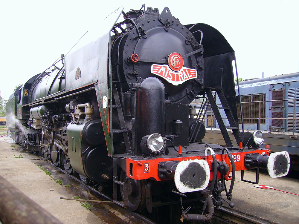
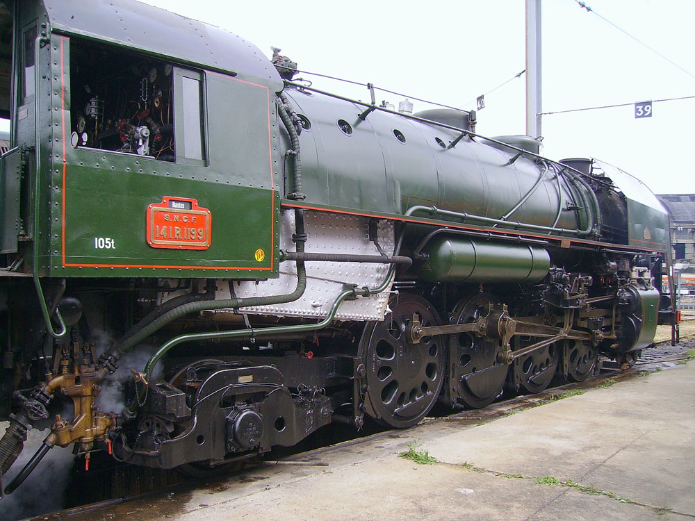
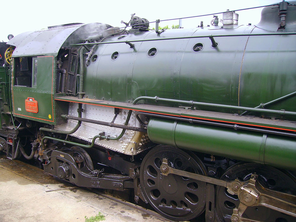
Preserved 141-R 1199 sits at the Vailleneuve-Saint-Georges on May 5, 2007. Didier Duforest Photo - Wikimedia Commons

Preserved 141-R 1199 sits at the Vailleneuve-Saint-Georges on May 5, 2007. Didier Duforest Photo - Wikimedia Commons

CSR will be releasing its newest White Paper, the Development of Modern Steam 4: Advanced Internal Water Treatment, to its Supporters later this week (one benefit of being a CSR Supporter is receiving advanced copies of White Papers). The paper will be released to the public in mid-February.

On this #TechTuesday, we wanted to take a moment to discuss the unique history of French State Railways'(SNCF) Class 141-R, a series of more than 1,300 U.S.- and Canadian-built 2-8-2's used overseas. Covered in greater detail in the upcoming White Paper, the 141-R served as test bed locomotives for an advanced internal boiler water treatment that eventually led the way to that which CSR's Director of Engineering Shaun McMahon has been utilizing in locomotives for the past 24 years. Of note is that this predecessor treatment resulted in a 90% reduction in boiler maintenance, allowing the locomotives to operate in excess of 1,000,000 kilometers with next-to-no boiler maintenance issues!

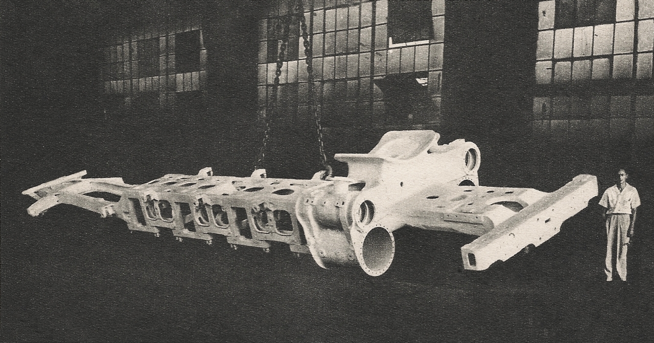
General Steel Castings advertisement from the era - click to enlarge.

When the French entered the World War II, the country had more than 17,000 operable steam locomotives to haul its trains - shortly after Liberation, however, only 3,000 remained in operation. The SNCF needed a rugged, light-weight, and powerful dual-purpose locomotive to aid in reconstruction, and they turned to North America for a solution.

That solution evolved into the 141-R, a 256,000 pound 2-8-2 (known as 141 in France where steam engine configurations are designated by axles not wheels) that could pump out 44,500 pounds of tractive force through its 65 inch driving wheels. These locomotives were without a doubt the most advanced 2-8-2's ever manufactured in mass quantity (1,340 were manufactured by a combination of ALCO, LIMA, Baldwin, and MLW between 1945 and 1947, but 17 were lost at sea with their ship during a storm).

This comparison of drawbar horsepower between Kylchap and standard exhaust speaks to the benefits of proper steam handling - click to enlarge.

Locomotives 141 R 1 - 141 R 1100 featured traditional U.S.-style bar frames, spoked driving wheels (save for the main drivers, which were Boxpok) and roller bearings on lead and trailing trucks, as well as on the tender trucks. The exciting developments came with 141 R 1101 - 141 R 1340, which were equipped with the latest in technologies, including:

  • One-piece cast steel frame;
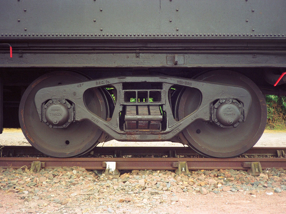
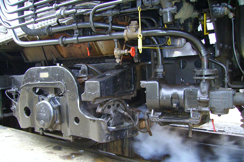
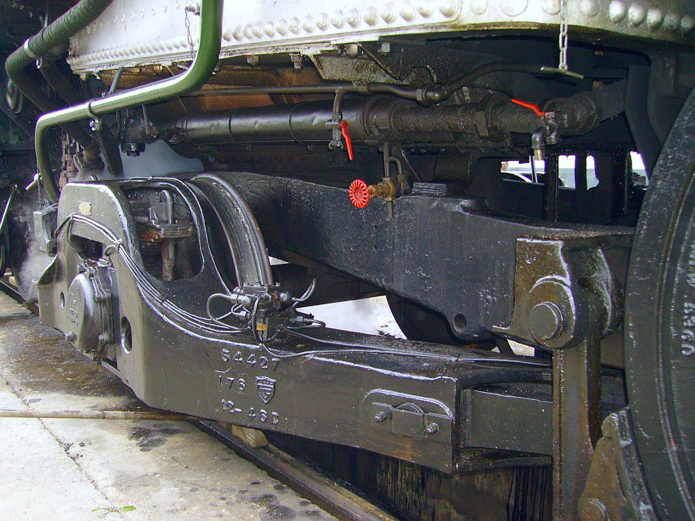
  • Roller bearings on all engine and tender axles;
  • Boxpok wheels on all driving wheels;
  • Chapelon-invented "Kylchap" Exhausts straight from the factory;
  • Open-type feedwater heaters;
  • North American multiple throttle front end; and
  • All other advances afforded to larger locomotives in the U.S. and Canada at the time.

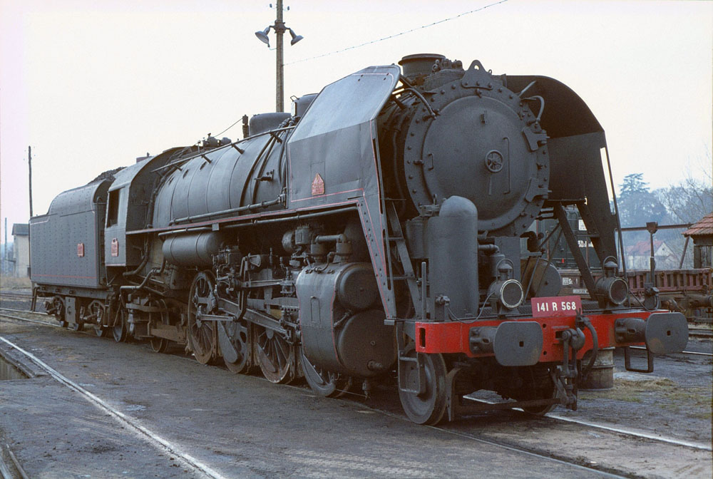
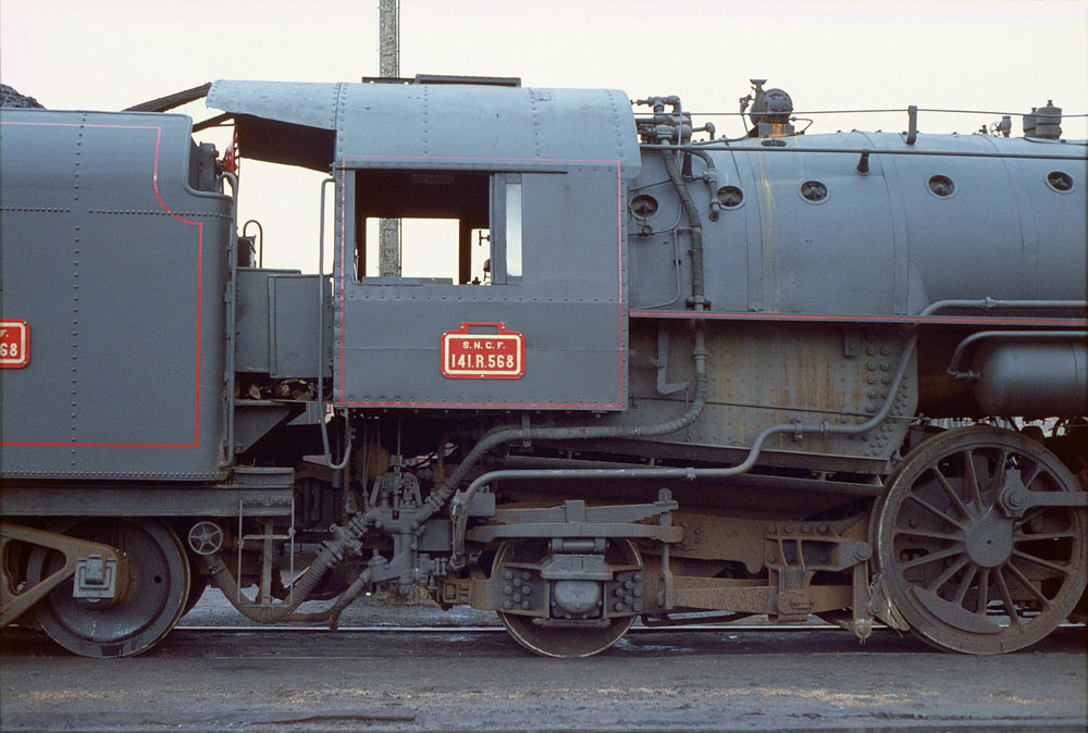
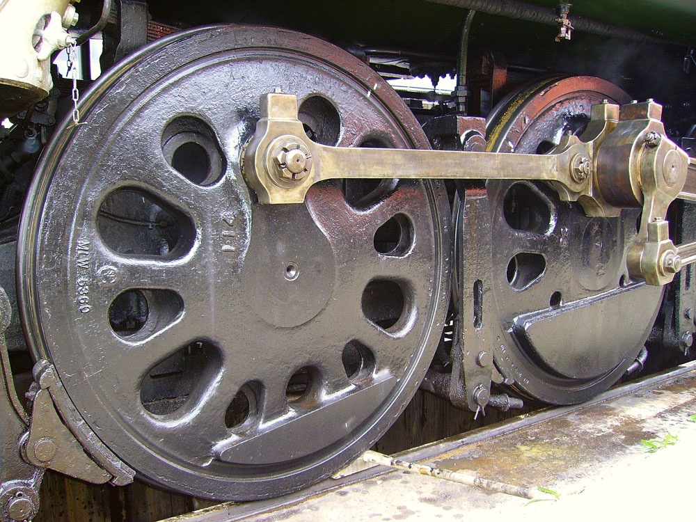
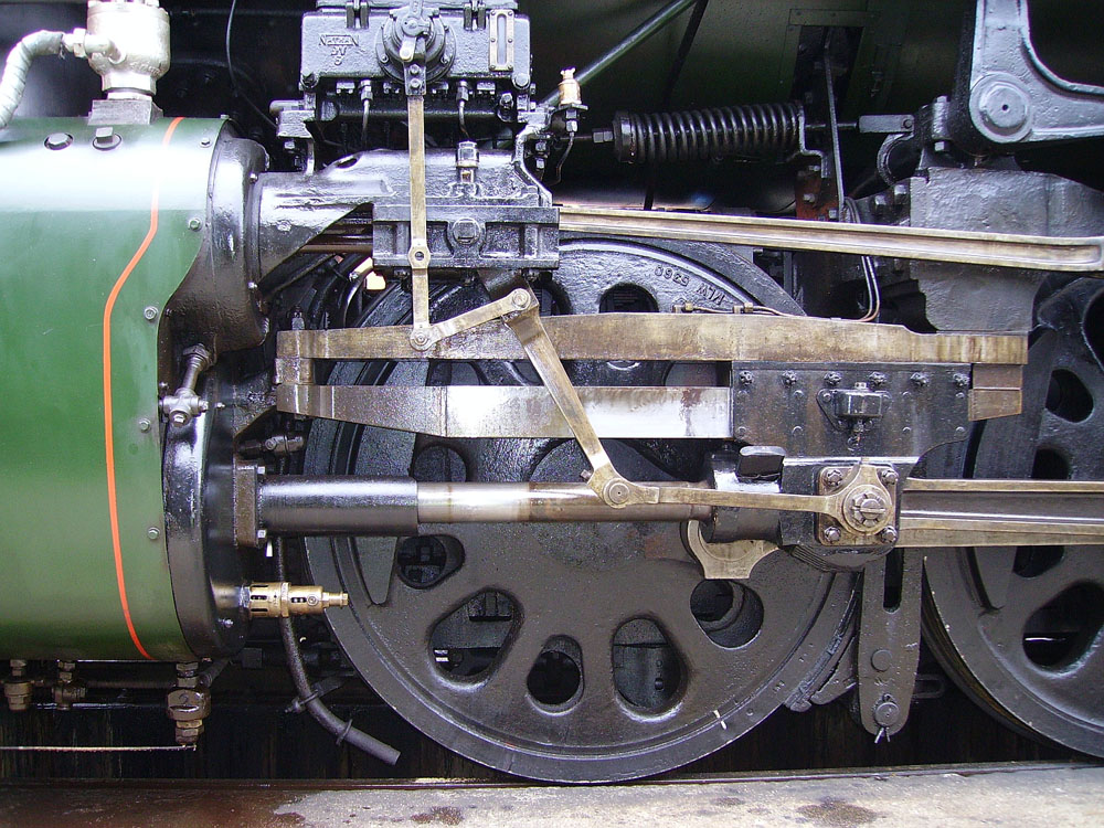
The photographs below, courtesy of Creative Commons, show many of the advanced features of the 141-Rs.

The locomotives were found to be incredibly reliable and robust by many at SNCF. At the time, many locomotives previously in service in France had been of more-than two cylinder design, often compounded with inside and outside cylinders (see CSR White Paper on Chapelon), which often led to higher maintenance costs.

By means of comparison, the following table shows the difference between the SNCF 141-R and Southern Railway 4501 here in the U.S.

CATEGORY SNCF 141-R 1199 SOU 4501
General Classification 2-8-2 2-8-2
Service Dual Service Freight
Fuel (Current) Oil Coal
Builder Baldwin Baldwin
Year Built 1947 1911
Tractive Force, lbs. 44,500 53,900
Weight in Working Order, lbs. 256,000 272,900
Length, Wheelbase, locomotive, ft.-in. 79-2 77-1
Boiler Pressure, lbs. (Designed) 220 205
Firebox Grate Area, Sq. ft. 55.5 54
Engine (Bore x Stroke), in. 23.5 x 28 27 x 30
Driving-wheel Tread Diameter, in. 65 63

The 141-R locomotives operated on SNCF from 1945 until 1975. Fortunately a number of 141-R's have been preserved, of which at least six, four in France and two in Switzerland, are in operational condition. The video below shows one of the Swiss locomotives in service a few years ago.

Check Out 141-R 1244 In Action in 2012

Stay tuned for the release of CSR's newest White Paper in mid-February.

New CSR White Paper

CSR released today a new White Paper that outlines the thermo-mechanical behaviors associated with steam locomotive fireboxes (including the firebox sheets, tube sheets, tubes and staybolts). This technical paper was originally written by modern steam engineer Livio Dante Porta in 1984 / 1985 during his work on the ACE 3000 modern steam project in the U.S. As such, the White Paper also includes information specific to tests undertaken with C&O steam locomotive 614 and issues it had with staybolt leakage.

This White Paper has been digitzed by CSR from the original hand drawn and hand written piece, with slight editing for clarity. Be sure to read it, and all of the other CSR papers, on the CSR White Paper Program page.