General News

A Primer on the Lempor Exhaust

While we have mentioned the Lempor in some of our White Papers, and we will focus a new White Paper specifically on exhaust systems in the near future, the CSR Team thought it might be helpful to give some insights into the physics given that both Grand Canyon Railway steam locomotives No. 29 and No. 4960 are now back in service and that both have Lempor Exhausts designed by Nigel Day. 

This video, courtesy of Chris Zahrt, shows GCRy No. 29 hustling a train under stormy skies. The 1906-built 2-8-0 burns used vegetable oil and employs a Lempor Exhaust to use steam as efficiently as possible within the constraints of the historic locomotive.

Understanding drafting in steam locomotives starts in the cylinder at the point of release [C on the following diagram]. This is when the valve first opens to let exhaust steam out of the cylinder. The pressure in the cylinder at release depends largely on the cutoff selected. A long cutoff means that the cylinder has been filled with near-boiler pressure steam for the majority of the stroke, which prevents the steam from expanding much before exhaust, therefore leading to a higher pressure at release. A short cutoff allows steam to enter the cylinder for a shorter percentage of the stroke, providing a proportionately longer percentage of the stroke for the steam to expand and, thus, exhausting with a lower pressure. Regardless of the pressure at the release point, the steam pressure in the cylinder drops quickly as the steam flows out and fills the exhaust steam passages [E]. The pressure at the cylinder exit [C] will eventually stabilize to a level determined by the total cross-sectional area of the exhaust nozzle(s) and the mass flowrate of steam. This stabilized pressure is known as "back pressure."

CLICK TO ENLARGE This diagram compares a "Normal" U.S. exhaust nozzle system with the advanced "Lempor" system, as equipped on GCRy Nos. 29 and 4960. Both types share similar components of: 1) Branch Pipes [live steam]; 2) Valves [live and exhaust stem]; 3) Piston [live and exhaust steam]; and 4) Exhaust passage. Where they differ is the design of: 4A/4B) the exhaust paths; 5A/5B) the type of nozzle; 6A/6B) the design of the petticoat; and 7A/7B) the refinement in design of the stack.

Between the cylinder [3 in the diagram above] and the exhaust nozzle [5A], some of the energy left in the steam will be lost due to factors such as: passages being too small; turns being too sharp; sudden changes in passage size; passages walls being too rough; or excessive heat loss due to design / lack of insulation. In some very poorly designed locomotives, the exhaust passages can be joined in ways such that the exhaust pressure pulse from one side of the cylinder can be "seen" by the opposite cylinder which creates an artificially higher back pressure [as exhibited above near the number 4A].

Bernoulli's equation helps us understand the relationship of pressure and velocity in fluid flows. Without delving too deeply into the details, the equation tells us that a high speed flow equates to a lower pressure and a low speed flow leads to higher pressure. Taking a look at the locomotive exhaust nozzle [5A], the idea is to transfer the "pressure energy" of the steam into velocity to create a low pressure region just outside the nozzle which will suck the exhaust gasses from the firebox through the flues. For a given back pressure, a smaller nozzle opening (aka "cross-sectional area") will give a higher velocity flow and, thus, a strong draft on the fire. However, that back pressure may become high enough to start limiting the power that can be produced in the cylinders. This is exhibited in the relationship between the difference in pressure going in and going out of the cylinders. 

Normally, to get more power, one would simply increase the cross-sectional area of the nozzle opening, lowering the back pressure at the same cylinder inlet pressure and cutoff. While this may increase power, it decreases the velocity of steam exiting the nozzle and, in turn, also decreases the draft acting on the fire and drawing hot gasses through the boiler. The result would be a poorly-drafting locomotive that would have difficulty making steam to meet the improved power from the cylinders.

Whereas the above describes a traditional single nozzle exhaust, a Lempor nozzle splits the total steam flow between four separate, smaller nozzles [5B]. Assume that the total cross-sectional opening for the four Lempor nozzles is the same as a single nozzle [5A]. Under the same inlet pressure and other conditions, the local speed of the steam jet exiting the smaller openings of the four nozzles will be a fair bit higher that that of the single, larger nozzle, simply because of the relationship between opening size and velocity. This creates a stronger draft with the same back pressure. The steam locomotive designer now has more options for finding an optimal balance between cylinder power and draft.

Steam locomotive mechanical engineer L.D. Porta also introduced a converging-diverging, or DeLaval, nozzle to steam locomotive design [5B]. In all other steam locomotive exhaust nozzles that we are aware of prior to his application, the exit walls were essentially parallel to the direction of steam flow. Under subsonic conditions, the converging or narrowing section works to speed up the flow. Once the flow reaches choked conditions, basically a velocity of Mach 1, no further acceleration can be obtained and thus no more improvement in draft. The diverging, or widening, portion of the nozzle under subsonic conditions actually serves to slow down the flow and increase the pressure. However, things flip-flop once the flow goes supersonic and by allowing the nozzle to widen to the outlet, the steam jet can continue to accelerate leading to draft improvement.

The multiple nozzles also help with mixing of the steam and flue gas as they lead to more surface area of steam at high velocity in contact with the flue gas. [Note that without good mixing of the two streams, the flue gas would mostly just stay in the smokebox instead of exiting the stack and its velocity through the flues and tubes would be much lower, resulting in poor heat transfer and thus poor steaming.] While mixing takes place as soon as the steam exits the nozzle, the first section of the petticoat [6B] is specifically thought of as a mixing chamber and its proportions in concert with those of the nozzles help assure good mixing/momentum transfer from the high velocity steam to the lower velocity flue gas.

Once mixed, the steam and flue gas is in the subsonic flow region but still has a fair bit of energy left and is still flowing at a fairly high velocity. If it was just allowed to go up a straight stack to the atmosphere [7A], that energy would be lost. Therefore, the latter part of the Lempor petticoat widens out [7B], which slows the flow and increases its pressure back to that of atmospheric. This characteristic, widening stack can be seen in the diagram of No. 29 below.

As in much of fluid mechanics, it takes very careful calculation and proportioning to maximize the benefit of the system which can be significant compared to other known exhausts. Failure to do so, either through poor engineering or when physical or other constraints restrict the designer's ability to implement a properly sized system will lead to a poor performing product.


Upcoming White Paper

The CSR Team is working on a White Paper dedicated to the development of advanced steam exhaust systems, from the traditional U.S. designs through Chapelon to Giesel and Lempor. Expect more information on that in the coming month. To stay up to date on CSR, consider signing up for our email list at the bottom of this page.

Footage of First Torrefied Biomass-Run Train

This video shows the first run of the torrefied biomass test train on the Milwaukee County Zoo mainline, with footage of the train starting from the point the shop lead connects with the tracks and operating to the summit, approximately 1/2 mile. We have synced up the readings from the four thermocouples with the video footage, showing a second-by-second readout of combustion temperatures in the locomotive.

While watching the video, note that Zoo crew member, Ken Ristow, is hand shoveling loads of the small, torrefied biomass pellets into the firebox. The fuel pellets, which were graciously donated to CSR for these tests by New Biomass Energy, are much smaller than the coal typically used on a steam locomotive. We therefore modified the grates with stainless steel mesh to prevent the fuel from falling through the large pinholes. Due to the small size of the fuel, we could only build up a thin firebed (2" with biomass vs. 5" on coal), meaning there was less potential energy in the fire, resulting in the need to shovel more frequently than with coal. Likewise, NBE's pellets exhibited such good flowability, which is very important in stoker firing, that they were prone to slide off of the coal scoop.

CSR is working with research collaborator Natural Resources Research Institute and the Milwaukee County Zoo to schedule another round of testing later this year with larger, "puck" sized torrefied biomass briquettes to further verify the promising results produced from these initial tests. Likewise, we have been in discussion with standard gauge steam operators about performing full size tests in the future.

In all, the Milwaukee County Zoo tests were an extremely important scientific and risk mitigation step in this research. They allowed CSR the opportunity to collect comparative data on the combustion of coal vs. torrefied biomass (which will be made available in the coming months as part of a larger White Paper) and it proved that steam locomotives could make steam and operate safely using the alternative fuel. 

We could not have done these tests without the outstanding assistance of the Milwaukee County Zoo, the Natural Resources Research Institute, New Biomass Energy, the American Boiler Manufacturers Association, and the support of CSR's donors, including generous contributions by Bon French and Fred Gullette.


If you'd like to help make the next set of tests happen, please consider:

CSR Undertakes First Test of Biocoal with a Steam Locomotive

Milwaukee County Zoo locomotive number 1924 served as the "guinea pig" on these first torrefied biomass tests. Operating on 15 inch gauge track, the locomotive is the perfect scale to begin combustion analyses of torrefied fuel under the highly vari…

Milwaukee County Zoo locomotive number 1924 served as the "guinea pig" on these first torrefied biomass tests. Operating on 15 inch gauge track, the locomotive is the perfect scale to begin combustion analyses of torrefied fuel under the highly variable drafting of steam locomotive boilers.

From June 10-12, CSR teamed up with the Milwaukee County Zoo, the Natural Resources Research Institute, and New Biomass Energy to undertake the first test of torrefied biomass on a steam locomotive. The tests are a key step in ensuring that the fuel can be used in steam locomotives of all sizes in the face of shuttering coal mines. 

Torrefied biomass pellets used in the testing.

The Milwaukee County Zoo operates two steam locomotives on its 15 inch gauge railroad. With just over a mile of mainline track and upwards of 30 trains per day, the Zoo operation provided CSR the opportunity to compare runs burning coal with identical runs burning "torrefied biomass," also known as "biocoal," in a controlled, test-scale environment.

"We instrumented the locomotive with four, Inconel-sheathed thermocouples to gauge firebed, combustion space, and exhaust gas temperatures when burning coal vs biocoal," explained CSR Senior Mechanical Engineer Wolf Fengler. "Tests were run on Saturday and Sunday, with trains Saturday burning coal and the first runs of Sunday burning biocoal."

Modified grates [bottom] and two of the three thermocouples poking through staybolt telltale holes [left]. Click to Enlarge

CSR worked hand-in-hand with Zoo staff to instrument 4-6-2 steam locomotive number 1924 and undertake the tests [see diagram below]. Torrefied biomass fuel was graciously donated by New Biomass Energy for use during research. The small fuel pellets were burned on a modified stainless steel grate installed by CSR on-site.

"We used National Instruments hardware in concert with its LabView software to record second-by-second temperature data from the sensors," said CSR President Davidson Ward. "Perhaps most exciting was the fact that three of the sensors were directly in the firebox, one submerged in the firebed and two at varying heights above, each of which provided better insights into the combustion behaviors of each fuel."

[Click to Enlarge]

While data processing is still underway, initial results indicate that the torrefied biomass fuel burns with a very similar temperature profile as the coal used by the Zoo, but the biomass had a much longer flame profile, which bodes well for producing more uniform stresses in the firebox.

The video below shows a comparison of coal with biocoal under identical, hostling circumstances. Note the length of flame and brightness of the fire generated by the torrefied biomass.

More information, including additional videos of the tests and a detailed White Paper, will be made available later this summer. CSR plans to undertake a second set of tests with the Milwaukee County Zoo with larger torrefied biomass pellets created by NRRI at its Coleraine Minerals Research Laboratory later this year. The organization has also been in discussions with standard-gauge operators about undertaking full scale tests in the future.

The Milwaukee Zoo train tests were made possible by the outstanding assistance of the Milwaukee County Zoo, the Natural Resources Research Institute, New Biomass Energy, the American Boiler Manufacturers Association, and the support of CSR's donors, including generous contributions by Bon French and Fred Gullette.

If you have yet to do so, please:


Dedicated to: Randy Rawson

For the duration of biofuel testing, CSR renamed locomotive 1924 "Randy Rawson" in honor of the former President of the American Boiler Manufacturers Association, W. Randall Rawson, who died in November 2013. He was a superb friend and advocate of CSR, having expressed unwavering interest and support of our biofuel and steam locomotive research. He had always wanted to be present for the first tests of torrefied biomass in a steam locomotive, and we wanted to do our part to honor him. To this day, Rawson's legacy, sense of humor, and enthusiasm continue to serve as an inspiration to the leaders of CSR. 

Axles vs. Axis - Memorial Day 2016

The U.S. railroads banded together with the nation to help win the Second World War, and a large portion of that included promoting war bonds and recognizing the accomplishments of the railroad in supporting the Allied war effort. This ad shows many pieces of the "Axles vs. Axis" of the ATSF, including an engineman lubricating the driving box pedestals of ATSF 3460. 

On this Memorial Day, CSR remembers and honors the ultimate sacrifice given by so many in support of freedom - from those who rode to the front lines behind ATSF steam locomotives to those who have defended our freedom before and since. To all, we are forever grateful.

NEW NRRI Paper - Use of Biomass Fuels with a Focus on Biomass Pre-Treatment

This new paper by CSR research collaborator Natural Resources Research Institute was authored by Don Fosnacht, Ph.D (a CSR Board Member) and his colleague David W. Hendrickson. It provides a very in-depth look at the way in which pre-treatment of biomass can be used in steam boilers to make electricity (or, in some cases, propulsion for trains). It is of great importance in serving as a "bridge" fuel to transition from coal to cleaner energy, lowering conversion costs at power plants.

The following executive summary provides a good overview of the paper, which can be downloaded in its entirety here.

The desire to fire biomass for electric power generation has recently been amplified by President Obama’s new Clean Power Plan with a call for a 32% cut in power plant emissions by 2030 from 2005 levels.

With carbon-capture and sequestration technology still developing, many coal plants are looking for alternative ways to reduce the CO2 from larger scale fossil fueled power plants. Some utilities have started mixing their coal with a cheap material such as woody biomass that could help them meet the expected EPA targets. Co-firing with wood and coal is becoming a viable ‘bridge strategy’ for increasing the use of renewable resources while reducing atmospheric CO2. Worldwide, over 200 test burns have been completed for co-firing wood with coal at large-scale coal fired power plants to show the feasibility of this technique to reduce CO2 in plant emissions.

Compared with fossil fuels, biomass has not been widely utilized in the electric power generation industry due to its relatively low energy density. Biomass pre-treatment technologies have therefore been developed to densify biomass into forms that can be stored and handled in a manner consistent with coal usage at power generation operations.(2) The biomass industry is currently focusing on biomass pretreatment technologies for either pelletizing raw biomass fuels or pelletizing torrefied biomass fuels. The wood pelletizing process for production of wood fuel pellets is a well-developed technology worldwide. The torrefied wood industry, however, is in a ‘development stage’ in that many torrefaction processes are being researched and refined, with no one technology perfected or preferred as yet.

The global electric power industry is thus seeking ‘refined’ renewable fuel products to partially or fully replace coal as its fuel source in order to reduce carbon and other significant emissions. ‘Refining’ is a generic term for different fuel processing technologies including steam explosion, torrefaction, and hydrothermal carbonization (HTC) (also called wet torrefaction). Through the use of torrefaction ‘mild pyrolysis process,’ a significant improvement in the suitability of biomass for co-firing in coal fired power plants is produced while providing the potential to enable higher co-firing percentages of biomass versus using untreated wood pellets. The quality of the torrefaction process depends on the balance between temperature and residence time to preserve a maximum of energy density to achieve certain fuel properties like grindability and hydrophobicity.(3) While the lignin content in wood is usually enough to bind pellets, other forms of biomass require special conditioning to strengthen them. Sometimes binders such as starch, sugars, paraffin oils, or lignin must be added to make the pelletized biomass more durable.(4) Pelletizing into a highly water repellent pellet or briquette is required for the torrefied wood industry to produce an acceptable coal replacement product that can be shipped in bulk in open containers and stored in a manner similar to coal. As of 2015, emerging biomass torrefaction companies have significantly improved their ability to produce high quality products with pellets of comparable durability to conventional wood pellets. Key areas of work remain, and these include: densification with and without binders to enhance the bulk density of the produced fuels, development of moisture resistance regimes to allow avoidance of indoor storage, optimization of the shape and size of the fuel products, and the degree of pretreatment required to reduce ash content and to achieve the desired fuel values in the products.

Southern Company, at its Gulf Power subsidiary, successfully tested the use of ‘white pellets’ that had undergone torrefaction in a mobile torrefaction facility. Even though the produced materials were not of ideal physical quality, the company showed that up to 100% coal substitution could be achieved. The company concluded that the use of torrefied materials was a straightforward path to substitution of increasing amounts of coal in power generation. Ontario Power in Canada has converted two plants in Western Ontario to completely use biomass materials. In one case, they modified the power plant to utilize white pellets, and the capital costs for this modification were estimated to be C$170,000,000. In the second case, the power plant decided to use advanced wood pellets produced from steam explosion processing methods (Zilkha or Arbaflame), and the capital costs to allow the materials to be used was only C$5,000,000. The capital cost reduction illustrated that the advanced wood pellets could be used like coal in that second plant example. Finally, a European economic analysis indicates that considering all aspects of potential fuel use, advanced wood pellets compared to ‘white pellets’ have a significant economic advantage when logistics and actual cost of use at the power plant is considered.

Modifications in Mainline Steam - The Red Devil

[Click to Enlarge]

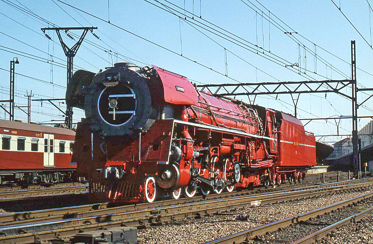
South African Railways (SAR) Class 26 number 3450 (nicknamed the "Red Devil"), is the product of mechanical engineer David Wardale’s 1981 rebuilding of a Class 25NC 4-8-4 steam locomotive.  The rebuilding, performed at the Salt River Works in Cape Town, South Africa, was based on the works of the Argentinian mechanical engineer L.D. Porta, with whom Wardale corresponded during the modification.

The SAR Class 25 and 25NC 4-8-4’s were a group of 140 locomotive purchased by the South African Railways, delivered between 1953 and 1955 by Henschel and Sohn as well as the North British Locomotive Company. These locomotives featured all the then-contemporary American improvements: one piece cast steel frame with integral cylinders, roller bearings on all axles and motion, as well as mechanical and pressure lubrication.  The last built Class 25NC, number 3450, entered service in 1953 built by Henschel and Sohn, construction No.28697.

Even though SAR management had already decided to replace all steam traction with electric and diesel-electric power, Wardale was determined to show that the efficiency of steam locomotives could be greatly increased.  With the help of Argentinian mechanical engineer L.D. Porta, Wardale set about on a major modification program including the installation of the Gas Producer Combustion System (GPCS) to improve combustion efficiency and the Lempor exhaust system to improve the power output of the cylinders.

At the end of 1979, the rebuilding of number 3450 to Class 26 began.  Several SAR mechanical facilities were involved in producing new parts of modifying existing parts, including: Salt River in Cape Town, Bloemfontein, Beaconsfield in Kimberley, Koedoespoort in Pretoria and Pietermaritzburg.  The modification work had three main goals: 1) improve the combustion efficiency and increase the steam production, 2) reduce smoke emissions and 3) eliminate clinker problems in the firebox.

Following is a list of the principle modifications to the locomotive:

  • Double Lempor Exhaust;
  • Closed Type Feedwater Heater;
  • Enlarged Steam Chests;
  • Enlarged Branch Pipes;
  • Larger Superheater and Front-End Throttle (From a SAR Class GMAM Garratt);
  • Superheat Booster;
  • New Design Piston Valves;
  • Articulated Valve Spindles;
  • Cooled Valve Liners;
  • Diesel-type Piston Rings;
  • Improved Steam Ports;
  • New Design Cylinder Liners;
  • New Design Pistons;
  • Modified Valve Gear;
  • Tender Coal Capacity Increased by 2 Tons;
  • Lengthened Smokebox;
  • Air Sanding;
  • Self-Cleaning Smokebox;
  • New Design Valve and Piston Rod Packings;
  • Cutoff Proportional Lubrication;
  • Modified Insulation;
  • Exhaust Deflectors and
  • Bright Red Paint.

During testing, the locomotive proved capable of achieving nearly 5,000 DBHP, believed to be the highest output attained by any locomotive on Cape Gauge (3'-6").  In comparison, the Red Devil was capable of the following improvements against a standard Class 25NC:

  • 28% Reduction in Coal Consumption;
  • 30% Savings in Water Consumption and
  • 52% Increase in Drawbar Horsepower.

Equally impressive is that the locomotive ended up being cheaper to maintain and operate than diesel-electric locomotives on the railroad, due in large part to its modern construction, the low cost of fuel, and the application of advanced water treatment.

The following table provides a comparison between the Red Devil and other locomotives in operation today.

CATEGORY Southern 4501
As Rebuilt by
TVRM in 2014
SAR Class
25NC
(Unmodified)
SAR Class 26
No. 3450
"Red Devil"
ATSF 3751
As Rebuilt by
ATSF in 1941
General Classification 2-8-2 4-8-4 4-8-4 4-8-4
Cylinders, in. 26.625 x 30 24 x 28 24 x 28 30 x 30
Drivers, in. 63 60 60 80
Boiler Pressure, lbs. 205 225 225 230
Grate area, Sq. ft. 54 70 70 108
Engine weight, lbs. 272,940 214,400 222,400 478,100
Heating surface, Sq. ft. 3,231 3,390 3,104 5,634
Superheater, Sq. ft. 600 630 1,014 800
Drawbar horsepower, hp. 2,150 2,091 4,023 3,600
Power/Weight (dbhp/ton) 15.8 19.5 36.2 15.3
Tractive effort, lbs. 53,900 45,360 52,000 71,719
Builder Baldwin Henschel +
North British
Henschel Baldwin
Date (Rebuit) 1911 (2014) 1953-1955 1953 (1981) 1927 (1941)

It was announced earlier in 2016 that the Red Devil was moved from storage at Monument Station in Capetown to a restoration facility for restoration to operation. The locomotive is set to be used in conjunction with the Ceres Rail Company excursion operation, hauling trains on the mainline between Cape Town and Wolseley. It is unclear whether the locomotive, which had been significantly de-modified, will be rebuilt as a Class 25NC or converted back into a Class 26.